


- Product overview
- Frequency inverters
Frequency inverters
View offerDiscover our diverse range of AC drives, designed to meet a wide range of applications. From simple standard drives to drives for a specific application. Our range offers the perfect balance between price and performance. Whether you are looking for reliable solutions for industrial automation or have specific technical needs, we offer a diverse range with the optimal ratio between quality and cost-effectiveness.


- Power (KW): 0.75
- Phase: 3~400
- Current (Ampere): 3
- 130mm x 250mm x 170mm

- Power (KW): 0.75
- Phase: 3~400
- Current (Ampere): 3
- 161mm x 366.4mm x 199mm

- Power (KW): 0.75
- Phase: 3~400
- Current (Ampere): 3
- 161mm x 366.4mm x 199mm

- Power (KW): 1.5
- Phase: 3~400
- Current (Ampere): 4
- 130mm x 250mm x 170mm

- Power (KW): 1.5
- Phase: 3~400
- Current (Ampere): 4.2
- 161mm x 366.4mm x 199mm

- Power (KW): 1.5
- Phase: 3~400
- Current (Ampere): 4.2
- 161mm x 366.4mm x 199mm

- Power (KW): 2.2
- Phase: 3~400
- Current (Ampere): 6
- 130mm x 250mm x 170mm

- Power (KW): 2.2
- Phase: 3~400
- Current (Ampere): 6
- 130mm x 250mm x 170mm

- Power (KW): 2.2
- Phase: 3~400
- Current (Ampere): 5.5
- 161mm x 366.4mm x 199mm

- Power (KW): 2.2
- Phase: 3~400
- Current (Ampere): 5.5
- 161mm x 366.4mm x 199mm

- Power (KW): 3.7
- Phase: 3~230
- Current (Ampere): 17
- 130mm x 250mm x 170mm

- Power (KW): 3.7
- Phase: 3~400
- Current (Ampere): 9
- 130mm x 250mm x 170mm
Fequently asked questions
- Smooth start and stop; by allowing motors to start and stop gradually, you reduce mechanical shocks and reduce wear. As a result, you reduce the peak load on the mains during start-up in particular.
- Variable speed control; you can infinitely adjust the speed of a motor. This is especially important in applications where the motor speed is tuned to changing conditions.
- Energy-saving; because the motor does not constantly run at full speed, but is tuned to the necessary load, you can save energy.
- Improved precision; by precisely controlling motor performance, you can optimise processes and improve product quality.
- Preventing overload; an AC drive can protect motors from overload and damage with the right settings.
- Reverse direction of rotation; All our AC drives can reverse the direction of rotation of the motor. This can be useful in certain situations.
- PM control; they are also suitable for controlling permanent magnet motors.
The ME300 and MS300 series AC drives are compact and easy to set up. The drives have a control panel as standard. The drives have an analogue input for connecting a potentiometer or an analogue signal from, for example, a PLC.
There are 16 adjustable presets in the drive via 4 digital inputs. The drives can be controlled with hard contacts, but also via a PLC output (NPN or PNP), adjustable via a dip switch.
The IP rating, ‘International protection’, is an accurate method of indicating the degrees of protection of enclosures. This IP rating indicates the extent to which, for example, an AC drive is resistant to water and dust. Depending on the situation in which it is used, you need an IP Class that provides adequate protection.
The values are listed below:
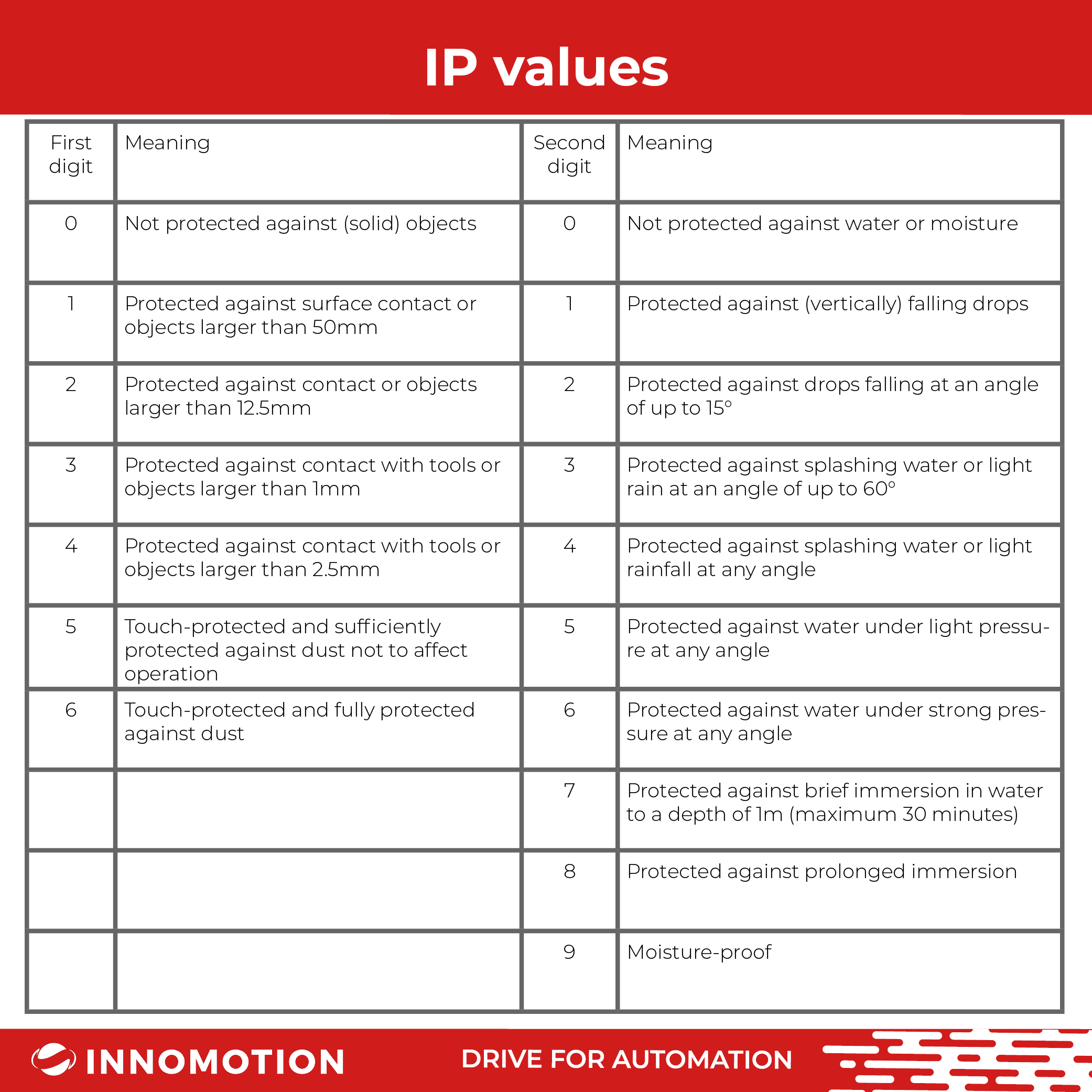
We can supply AC drives from IP20 to IP66. Frequently used for pumps is the CFP series with IP55 housing. This can easily be installed outside a cabinet.
Veel elektromotoren hebben tegenwoordig een ingebouwde PTC, De weerstand van deze PTC word hoger als de tempratuur van de motor toeneemt. In tegenstelling tot een PT100 kun je niet exact de tempratuur meten. De regelaar heeft een analoge ingang waar de PTC op binnenkomt. Wanneer deze een bepaalde waarde bereikt schakelt deze de motor af of geeft hier een melding van op het display.
Many electric motors nowadays have a built-in PTC. The resistance of this PTC increases when the temperature of the motor increases. Unlike a PT100, you cannot measure the temperature exactly. The controller has an analogue input where the PTC enters. When it reaches a certain value, it switches off the motor or gives a message on the display.
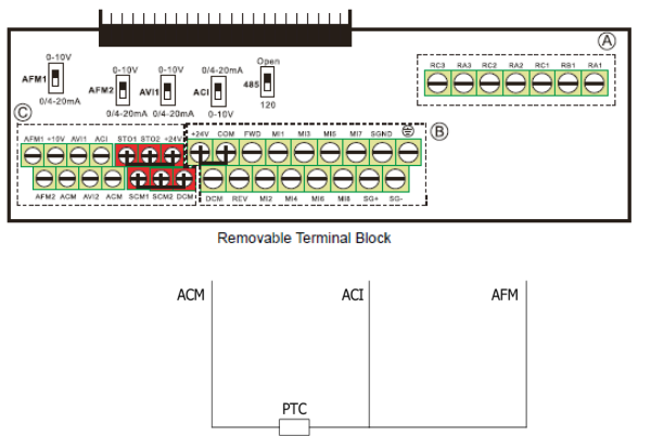
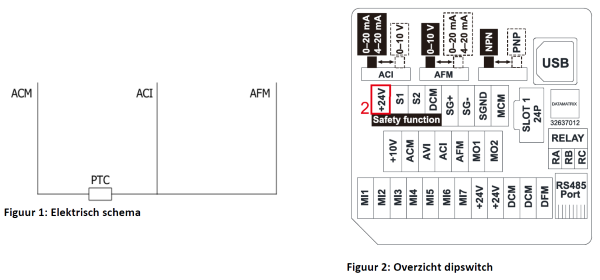
Schematic diagram
By connecting Figure 1: Electrical schematic, the PTC can almost be put into operation. For this, some parameters still need to be changed. More about this is described in Parameters.
AFM is the analogue output, ACI is the analogue input, ACM is ground. The AFM2 sends out a constant current.
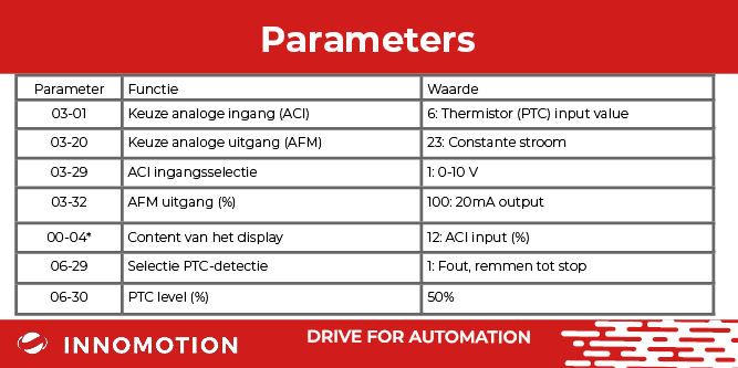
To get everything working properly, 2 dipswitches need to be flipped for an overview. The dipswitch of ACI has to be set to 0/4-20mA . This means that the ACI measures current. The AFM's dipswitch should be set to 0/4-20mA . This means that the analogue output emits a current.
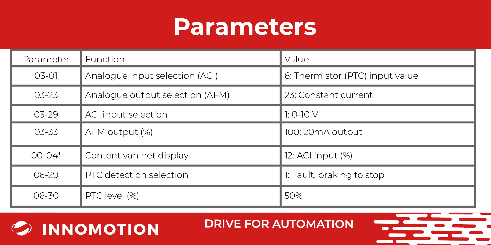
*optional parameter
The ACI input should be set as a PTC input. If the value of this input exceeds parameter 06-30, the motor switches off. Whether the motor switches off depends on parameter 06-29.
To monitor the input, it is possible to display this value on the start screen of the drive. You can do this by setting parameter 00-04 to 12. This value is in percent.
The switch-off point can be shifted using parameter 06-30. At 50%, the outside of the motor is about 75-85 °C.
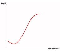
Due to the characteristics of the PTC, the difference between 50% and 51% is much greater than between 30% and 35%.
Many electric motors today have a built-in PTC, the resistance of this PTC increases as the temperature of the motor increases. Unlike a PT100, you cannot measure the temperature exactly. The MS300 has an analogue input where the PTC enters. When it reaches a certain value, it switches off the motor or gives a message on the display.
Diagram
By connecting Figure 1: Electrical schematic, the PTC can almost be put into operation. For this, some parameters still need to be changed. More about this is described in Parameters.
AFM is the analogue output, ACI is the analogue input, ACM is ground. The AFM sends out a constant current.
To get everything working properly, 2 dipswitches have to be switched for an overview see Figure 2: Dipswitch overview. The ACI dipswitch should be to the left. This means that ACI measures current. The AFM's dipswitch should be set to the right. This means that the analogue output emits a fixed current.
*optional parameter
The ACI input should be set as a PTC input. If the value of this input exceeds parameter 06-30, the motor switches off. Whether the motor switches off depends on parameter 06-29.
To monitor the input, it is possible to display this value on the start screen of the drive. You can do this by setting parameter 00-04 to 12. This value is in percent.
The switch-off point can be shifted using parameter 06-30. At 50%, the outside of the motor is about 75-85 °C.
Due to the characteristics of the PTC, the difference between 50% and 51% is much greater than between 30% and 35%.
What is the 87Hz principle and when do you apply it ?
The 87Hz principle (also called the √3 principle) can be applied to maintain torque at a frequency higher than the motor's base frequency.
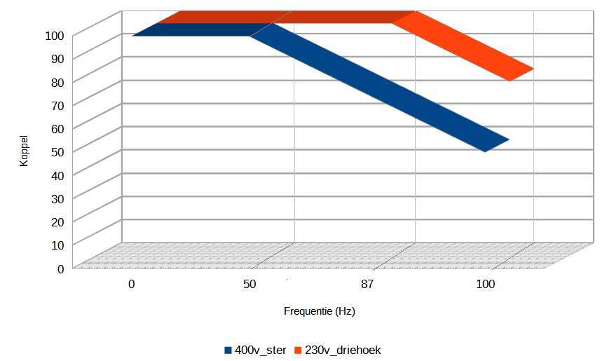
A standard AC motor 50Hz/400V (connected in star) delivers its rated torque up to 50Hz. At frequencies above 50Hz, torque decreases.
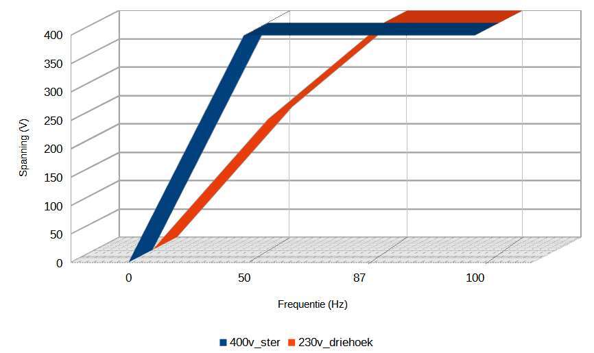
Up to a frequency of 50Hz, frequency and voltage are controlled, from 50Hz onwards, only frequency is increased and voltage remains 400V.
If a voltage of 400V is output at 50Hz, then at 25Hz the output voltage is 200V. The ratio of voltage to frequency is then constant (400/50 = 8V/Hz and 200/25 = 8V/Hz).
If the frequency is increased further to e.g. 80Hz, then, since the voltage is not increased further, this ratio becomes 400/80 = 5V/Hz.
This causes the motor to go into the so-called field weakening mode and the torque decreases inversely with speed. For example, when the speed doubles (100Hz), the torque is half.
In many cases, the lower torque is not such a problem, but sometimes it is important to maintain nominal torque at frequencies above 50Hz. In such cases, you can apply the √3 principle.
What are the conditions for applying this principle ?
In order to use a motor and frequency converter in this way, there are some conditions:
- The motor must be wound for 230V_delta/400V_star and be suitable for 87Hz.
- The motor (and the implement connected to it) must be mechanically suitable for the higher speeds. (Almost always a 4-pole-1500 rpm motor is used for this purpose).
- Operation above 50 Hz is for shorter periods.
- Because of additional losses in the motor, the thermal load is higher. We recommend monitoring the motor for temperature, e.g. with PTCs. Depending on the application, in certain cases it may be better to choose the motor one or two steps larger.
- The AC drive should be suitable for the current at triangular connection of the motor. For example, for a 2.2kW motor, the inverter must become √3 x 2.2kW = 3.81kW = 4kW.
How do you connect the motor ?
By connecting the motor in triangle and setting the inverter differently, the frequency can be increased to 87Hz while still delivering almost the rated torque.
The larger control range gives the machine or implement more flexibility. A 4-pole motor with a nominal speed of e.g. 1440 rpm at 50 Hz, then turns 2505 rpm at 87 Hz.
How is the frequency inverter set?
The frequency converter is set so that the voltage-frequency ratio remains constant up to a frequency of 87 Hz.
To do this, the base frequency of the inverter is set to 87Hz. This means that the voltage of 400V is reached at 87Hz. It follows that at a frequency of 50Hz, the voltage is 230V.
With this technique, frequency and voltage are controlled over the entire range 0 - 87Hz. The ratio of voltage to frequency is constant over this entire range and so the torque also remains constant up to 87Hz.
Parameters to be set:
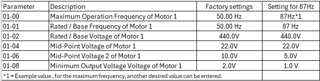
This principle is usually applied to 50Hz motors, for 60Hz motors this √3 principle can also be used. Then the base frequency is set to 60 x √3 =104Hz.