Nehmen Sie einfach Kontakt mit uns auf. Sie können uns werktags zwischen 08:30 und 17:00 Uhr erreichen.
How do I connect a PTC to an MS300?
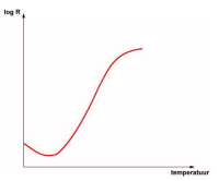
Many electric motors today have a built-in PTC, the resistance of this PTC increases as the temperature of the motor increases. Unlike a PT100, you cannot measure the temperature exactly. The MS300 has an analogue input where the PTC enters. When it reaches a certain value, it switches off the motor or gives a message on the display.
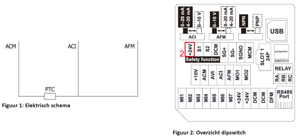
Diagram
By connecting Figure 1: Electrical schematic, the PTC can almost be put into operation. For this, some parameters still need to be changed. More about this is described in Parameters.
AFM is the analogue output, ACI is the analogue input, ACM is ground. The AFM sends out a constant current.
To get everything working properly, 2 dipswitches have to be switched for an overview see Figure 2: Dipswitch overview. The ACI dipswitch should be to the left. This means that ACI measures current. The AFM's dipswitch should be set to the right. This means that the analogue output emits a fixed current.
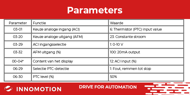
*optional parameter
The ACI input should be set as a PTC input. If the value of this input exceeds parameter 06-30, the motor switches off. Whether the motor switches off depends on parameter 06-29.
To monitor the input, it is possible to display this value on the start screen of the drive. You can do this by setting parameter 00-04 to 12. This value is in percent.
The switch-off point can be shifted using parameter 06-30. At 50%, the outside of the motor is about 75-85 °C.
Due to the characteristics of the PTC, the difference between 50% and 51% is much greater than between 30% and 35%.